TNC Series
Specifications
Electrical:
|
Impedance |
50 ohm |
75 ohm | ||
|
|
0 - 4 GHz |
0 - 1 GHz | ||
|
Working Voltage |
500 VRMS max. |
500 VRMS max. | ||
|
Dielectric Withstanding Voltage |
1500 VRMS min. |
1500 VRMS min. | ||
|
VSWR |
Straight |
1.3 max |
1.3 max | |
|
Right Angle |
1.5 max |
1.5 max | ||
|
Contact Resistance |
Center Contact |
3 Milliohms Max. |
3 Milliohms Max. | |
|
Outer Contact |
2 Milliohms Max. |
2 Milliohms Max. | ||
|
Insulator Resistance |
5000 Megohms min. |
5000 Megohms min. | ||
Material:
|
Parts Name |
Material |
Finish |
|
Body, Metal Parts |
Brass per QQ-B-626 |
Nickel plated |
|
Center Contacts |
Plug: Brass per QQ-B-626 |
Gold or Silver per requirement |
|
Jack: Beryllium copper per QQ-C-530 or Phosphor Bronze per QQ-B-750 or Brass per QQ-B-626 |
Gold or Silver per requirement | |
|
Insulators |
Teflon, Delrin, PBT polyester |
None |
|
Crimp Ferrules |
Annealed copper |
Nickel or Silver per requirement |
|
Clamp Gaskets |
Silicone rubber, Synthetic rubber |
None |
NOTE:Other Material/Finish is Available on
Request.
Mechanical &
Environmental:
|
Mating |
7/16-28 UNEF-2A threaded coupling |
|
Engagement Force |
2 in-lbs. max. |
|
Disengagement Force |
2 in-lbs. max. |
|
Coupling Nut Retention |
100 lbs. min. |
|
Coupling Proof Torque |
15 in-lbs.min. |
|
Contact Retention |
6 lbs. min. |
|
Durability(Mating) |
500 cycles min.(for Beryllium copper Jack contact only) |
|
|
-65°C to 165°C |
Vibration |
MIL-STD-202 Method 204 Test Cond.B. |
Salt
Spray |
MIL-STD-202 Method 101 Test Cond.B. |
Thermal
Shock |
MIL-STD-202 Method 107 Test Cond.B. |
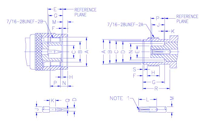
INTERFACE MATING
DIMENSIONS
|
PLUG |
|
|
JACK | ||||
|
Letter |
Millimeters |
|
|
Letter |
Millimeters | ||
|
Minimum |
Maximum |
|
|
Minimum |
Maximum | ||
|
A |
11.18 |
- |
|
|
A |
9.60 |
9.70 |
|
B |
Flared To
Meet Good Electrical
Contact |
|
|
B |
8.79 |
9.04 | |
|
|
|
C |
8.31 |
8.46 | |||
|
C |
4.83 |
- |
|
|
D |
8.10 |
8.15 |
|
D |
1.32 |
1.37 |
|
|
E |
- |
4.72 |
|
E |
5.33 |
5.84 |
|
|
F |
1.73 |
2.24 |
|
F |
0.15 |
0.46 |
|
|
G |
8.31 |
8.51 |
|
G |
5.28 |
5.79 |
|
|
H |
4.75 |
- |
|
H |
0.08 |
1.02 |
|
|
J |
4.72 |
5.23 |
|
J |
2.06 |
2.21 |
|
|
K |
- |
0.15 |
|
K |
1.98 |
- |
|
|
L |
4.95 |
- |
|
M |
- |
1.98 |
|
|
M |
2.06 |
2.21 |
|
N |
1.60 |
- |
|
|
N |
- |
6.50 |
|
P |
3.96 |
- |
|
|
P |
4.78 |
5.28 |
|
Q |
- |
0.64 |
|
|
R |
10.52 |
- |
|
|
|
|
|
|
S |
0.38 |
0.76 |
NOTE
1:I.D. TO MEET VSWR AND CONTACT RESISTANCE
WHEN MATED WITH 1.32/1.37 MM DIA. PIN.